- Fiber Optic Patch Cable
- MTP / MPO Fiber Patch Cable
- Armored Fiber Optic Patch Cable
- Mode Conditioning Patch Cable
- Fiber Optic Pigtail
- Fiber Optic Loopback
- Fiber Optic Adapter
- Fiber Optic Attenuator
- Fiber Media Converter
- Fiber Optic Transceiver
- Direct Attach Copper Cable
- Active Optical Cable / AOC Cable
- Ethernet LAN Cable
- Server Network Adapter
50/125 OM3 Mode Conditioning Fiber Optic Patch Cable
Product #: CAB-MOD-OM3Availability: In Stock
Leadtime: Usually ships in 2 days
Warranty: Lifetime
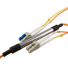
Mode conditioning patch cords are required where Gigabit 1000 Base-LX routers and switches are installed into existing multimode cable plants. These specialized cords help avoid Differential Mode Delay (DMD) effects that can occur when long wave transceiver modules operate at both single-mode and multimode wavelengths. The mode conditioning patch cord causes the single-mode transceiver to create a launch similar to a typical multimode launch.
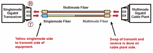
Our mode conditioning patch cords are custom made with any combination of LC, SC, ST, FC or MTRJ connectors at each end. A 9/125-singlemode fiber is offset to a multimode fiber on one leg while the other leg consists of a standard multimode fiber. The single mode/multimode side is plugged directly into the equipment. The duplex multimode side of the patch cord is plugged into the cable plant side.
Our mode conditioning patch cords are compatible with 850nm or 1300nm Gigabit Ethernet on standard multimode fiber, and a VCSEL laser source into standard multimode fiber. They are built to the IEEE802.3z application standard.
Things to know when using mode conditioning cables to patch an existing multimode cable plant to your Gigabit LX equipment.
1) Mode conditioning cable are normally used in pairs. That means that you will need a Mode Conditioning cable at each end to connect the equipment to the cable plant. So then these cables are usually ordered in even numbers. The usual reason why someone may order one cable is so they may keep it as a spare.
2) If your gigabit LX switch is equipped with SC or LC connectors, please be sure to connect the yellow leg (Singlemode) of the cable to the transmit side, and the orange leg (multimode) to the receive side of the equipment. It is imperative that this configuration be maintained on both ends. The swap of transmit and receive can only be done at the cable plant side. (see diagram below)

| Connector Type | Non-Conditioned Channel (Multimode) | Conditioned Channel (Singlemode/Multimode) | Ferrule Material | Housing Material | |
| Insertion Loss (dB) | |||||
| Maximum | Multimode Direction | Singlemode Direction | |||
| LC | <0.5 | <1.0 | >2.0;<22.0 | Ceramic | Composite |
| SC | <0.5 | <1.0 | >2.0;<22.0 | Ceramic | Composite |
| ST | <0.5 | <1.0 | >2.0;<22.0 | Ceramic | Metal |
| FC | <0.5 | <1.0 | >2.0;<22.0 | Ceramic | Composite |
| MTRJ | <0.5 | <1.0 | >2.0;<22.0 | Thermoplastic | Composite |
Write a review
Your Name:Your Review: Note: HTML is not translated!
Rating: Bad Good
Enter the code in the box below:


